Fill Holes
![]()
This function offers a varied range of commands allowing you to fill holes in CAD model geometries.
Access
- Click the
 icon in the Surfaces tab, or
 - Type Fill in the Quick Search input field.
Procedure
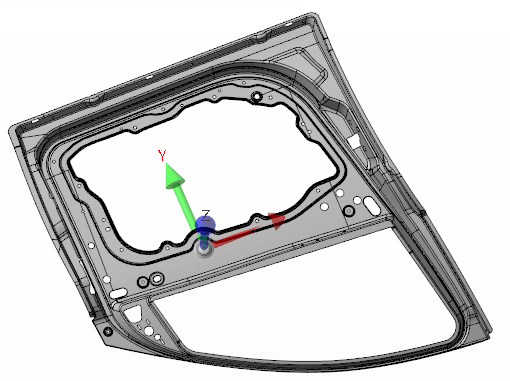
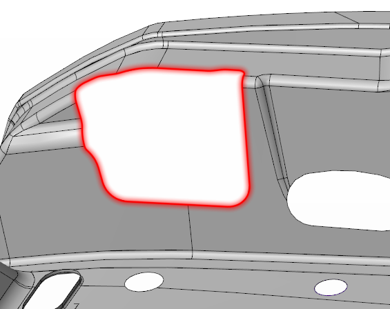
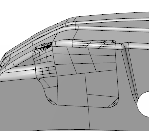
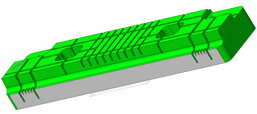
The following example, representing a car door frame, is one of the examples used to illustrate this function:
Once the function is launched, the first step is to determine the selection mode.
Selection
The different options are automatically displayed in the Environments pane of the Options ribbon:
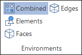
Combined and Elements - Enables the selection of complete solids and/or sheet elements depending on the selected filters.
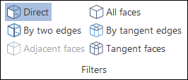
Faces - Enables selection by faces. Different Filters can be applied to determine the selection mode:
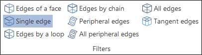
Edges - Enables selection by edges. Different Filters can be applied to determine the selection mode:
After selection and validation, the Options - Fill holes dialog box is displayed.
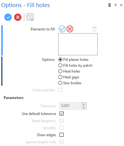
Options Dialog Box
Once the dialog box is activated there are some tools which allow you to dynamically select or remove entities for the current operation.
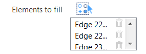
Clicking on the ![]() icon switches back into the selection mode allowing you to modify your selection by selecting/unselecting elements in the graphic area.
icon switches back into the selection mode allowing you to modify your selection by selecting/unselecting elements in the graphic area.
Clicking on the ![]() icon alongside an element allows you to remove it from the selection list.
icon alongside an element allows you to remove it from the selection list.
Use the ![]() icon (or Right Mouse click) to Validate your selection. The
icon (or Right Mouse click) to Validate your selection. The ![]() icon (or [Esc]) cancels the selection mode.
icon (or [Esc]) cancels the selection mode.
Options
Some options may not be available depending on the chosen selection mode.
|
Fill planar holes |
Fills planar holes on selected surfaces. If any of the holes are not planar, a message is displayed to alert the user and the operation is cancelled. |
|
Fill holes by patch |
Creates a patch over the hole according to the geometry of the surrounding surfaces. Activating the Unite patches option stitches the patched surfaces with the surrounding surfaces. |
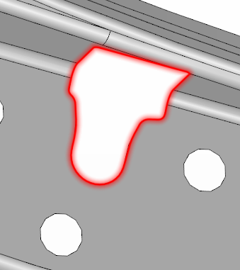
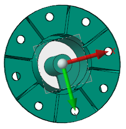
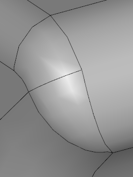
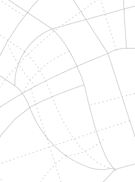
The following image shows a hole to be patched after selection by Peripheral edges:
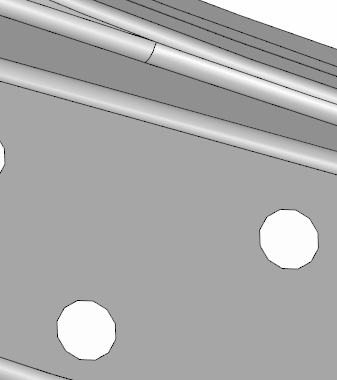
If the Keep tangency parameter is not activated, the result is as follows:
If Keep tangency is activated, the following result is obtained:
![]() Note: The Unite patches option is active for these two examples.
Note: The Unite patches option is active for these two examples.
|
Heal holes |
Fills holes by removing boundary trimming and takes into account the geometry of the surrounding surfaces to fill the hole. |
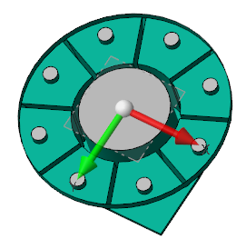
The example below shows a hole selected by Peripheral edges:
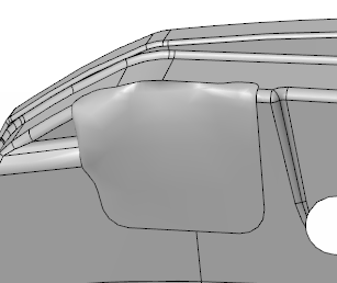
When the Heal holes option is selected and executed, the result is as follows:
|
Ignore largest hole |
This parameter applies to the three previously described options. It allows all holes to be filled except the biggest hole on the part. This parameter is used for filling holes on skins that do not represent a volume because, otherwise, the application will also try to close the external boundary of the part which would not give the desired result. |
The following part (showing top and bottom views) is used to illustrate this function:
When the Fill holes command is applied without activating the Ignore largest hole parameter, the whole area on the underside of the part (bottom view on the right in above screenshot) is filled.
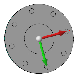
When the Ignore largest hole parameter is deactivated and the command is applied, the result is as follows.
All holes are now filled except the largest one on the underside of the part.
|
Heal gaps |
This option allows you to repair sheet bodies which have missing surfaces to make a closed body. |
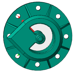
In the following example, surfaces are missing as indicated by the two red arrows:
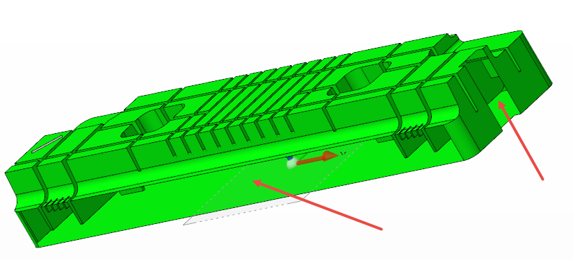
- Activate the Elements Environment option to select the whole part. Click anywhere on the part to select it and display the Options - Fill holes dialog box.
- Activate the Heal gaps option and click the Preview button. The following result should be obtained:
|
Sew bodies |
This option allows you to fill micro gaps in the geometry and close the entire surface to a solid. |
The following part is used for this example where a small gap exists in the area surrounded in red.
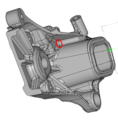
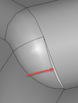
After zooming in on this area we can see the small gap that exists in the geometry indicated by the red arrow.
|
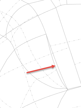
|
| Gap shown on geometry in shaded mode and in wireframe mode indicating a sheet body | |
- Deactivate the Use default tolerance parameter and enter 0.3 in the Tolerance input field immediately above.
- Select the complete part and press [Enter] to run the Sew bodies command.
If the Tolerance value is too small the gap is not detected.
You should obtain the following result.
|
|
| The gap is filled and the part is displayed as a solid in the wireframe mode | |
Top Toolbar
![]()
![]()
![]()
These two icons at the top of the dialog box allow you to Apply the current values or to Cancel the current function.
Preview generation is Automatic if this option is active in the dialog box menu accessed by clicking on the  icon. If this option is not active, click on the
  icon. If preview generation is not possible, the icon is greyed out.